Hybrid Networks
The technical content and drawings seen on this page are the work of Dr. R.G.Manton BSc(Eng), PhD, Ceng, MIEE. In recognition of this I have added his name to many of the drawings before sharing them on the UK Microwave Group WIKI. As an engineer working first at the BBC Research Department and then in BBC Transmitter Capital Projects, he prepared this information and circulated it to his colleagues for their information and education. As a long term associate of Dr. Manton I have no doubt that, had he lived into the internet age, he would have been pleased to be able to share his wisdom more widely.(G3YKI Jan 2021)
Contents
Hybrid Networks and their uses in radio frequency circuits
1. Introduction
Hybrid networks or diplexers have many uses in radio frequency circuits. What is not generally known is that these hybrids exist in many different forms. Configurations are as diverse as the Maxwell Bridge, the transmission line "3 dB coupler" and the waveguide "magic T". The circuit designer therefore has a choice of hybrids for a particular application. It is hoped that this report may help him to make the right choice and stimulate his ideas into finding new uses. The report describes the operation of hybrid networks in general, lists their uses, and gives circuit diagrams of different hybrids together with their electrical properties.
2. General
A hybrid network may be regarded from several points of view. From one point of view it looks like a bridge circuit fed by a generator, with two equal output loads and a balance load which receives power only if one of the output loads changes its impedance. A Maxwell bridge is one obvious example of this. However, it is not always easy to derive a general hybrid from a conventional bridge circuit and therefore the general hybrid will be considered instead from the point of view of a directional coupler, since this is closely related to a bridge. In general, a directional coupler has four ports, an input port A, one main output port B and two auxiliary output ports C and D which may be coupled to each other in the same way as A and B to form a symmetrical arrangement. This is symbolised in Fig. 1.
If power PA is fed into port A towards port B, which is perfectly terminated by a reflection-free load, a fixed fraction of power PC/PA is coupled into a matched load on port C. No power is transferred to port D. The remaining power PA-PC is transferred to port B. In Fig. 1 the main paths through the coupler are symbolised by full lines and the coupled paths are symbolised by broken lines. By symmetry, if power PB is fed into port B towards port A, which is terminated by a reflection-free load, an equal fraction of power, PD/PB, is coupled into a matched load on port D and no power is transferred to port C. The power ratio PC/PA, which is equal to PD/PB, is called the coupling factor k2. It is usually expressed in decibels.
Coupling = 10.log10k2 dB.
If the input power PA is split equally between ports B and C, PC/PA = k2 = ½, the coupling ratio is approximately -3dB and this particular directional coupler may be referred to as a hybrid. It is usually referred to as a "3 dB coupler" instead of a -3 dB coupler*.
More specifically, a hybrid may be defined as a linear passive circuit, generally with four ports which, when an a.c. signal is applied to any port, the other ports being terminated by non-reflecting loads, has the property that power is divided equally between only two of the remaining ports, the fourth port remaining isolated. This applies if any of the four ports becomes the input port. (This principle may also be extended to cover multi-port circuits in which power is equally divided between three or more output ports. The number of isolated balance loads is generally one less than the number of output ports).
In a perfect hybrid equal amounts of power should be transferred to the two output ports at all frequencies and a constant phase relationship should exist between them; the input of the circuit should be matched at all frequencies i.e. the normalised input admittance should be 1+ j0 and hence the input reflection coefficient should be 0%; the fourth port of the circuit should remain isolated at all frequencies provided that the output loads remain properly matched. Referring to Fig. 1, the measure of this isolation is expressed in dB as the ratio 10 log10(PD/PA). In a hybrid this is usually referred to as the "cross-loss". In directional coupler it is related to the "directivity" of the coupler.
3. Phase Relationships
The phase relationship between input and output signals depends on the circuit of the hybrid. Where all ports are unbalanced (one side earthed) two distinct types of hybrid exist, each being characterised by the phase difference between their output signals.
- a) 90° difference (quadrature).
- b) 0° or 180° depending on which port is used as the input port.
(Where one or more terminals are balanced or floating the phases of their voltages have an ambiguity of 180° and a convention must be established before absolute phase can be defined).
a) The convention used in this Report for a quadrature hybrid will be as follows:
Phase changes along signal paths are as indicated in Fig. 2. Power entering at port A results in half power at port C and half power lagging by 90° at port B. No power is transferred to port D provided that ports B and C are correctly matched.
b) The convention used in this Report for an unbalanced 0-180° hybrid will be as follows.-
As shown in Fig. 3, three paths have an equal phase delay, the fourth path DB has an extra phase delay of 180°. Ports A and D,and ports B and C are isolated as before.
Where the hybrid has one or more balanced terminals the diagram must be drawn as follows to denote the indetermination of phase on those terminals.
In most practical applications use can be made of either type of hybrid provided that it meets the power loading and bandwidth requirements and that the output phase relationships are correctly taken into account. This will be seen in Section 5.
4. Two Principal Functions of Hybrids
4.1 Power Dividing
A signal is applied to port A and is divided equally between ports B and C. The advantages of using a hybrid, as opposed to using a simple matched splitting transformer, are.-
a) The division of forward power remains equal regardless of the impedance seen at either output port. (This statement may seem absurd if one output port is matched and the other is open-or short-circuited, but it simply means that the backward powers are very different on the two ports although the forward powers remain equal).
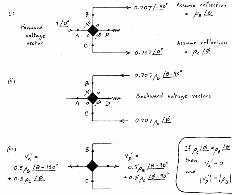
b) If a quadrature hybrid is used, equal reflections from the two output ports may be absorbed in the balance load leaving only the 'differences' between reflections to be seen at the input to the hybrid. This is best seen by considering what happens to voltage vectors:-
(This is the simplest way of analysing what happens in any circuit containing hybrids). The above analysis shows that the reflection coefficient seen at the input to a hybrid is generally less than the worst seen at either output port. With a simple splitting transformer it is possible for a 100% reflection on one output port to be seen as a 100% reflection at the input to the transformer thus causing an input transmitter to fail. This is less likely to happen if a suitably coupled hybrid is used.
4.2 Power Combining
The two signals to be combined are applied at ports B and C of the hybrid in appropriate phase relationship. The output power is delivered at port A.
Advantages of using a hybrid are:-
a) One generator is completely isolated from the other generator provided that the output port and balance load are correctly terminated. This implies that each input port remains matched regardless of the state of the second generator.
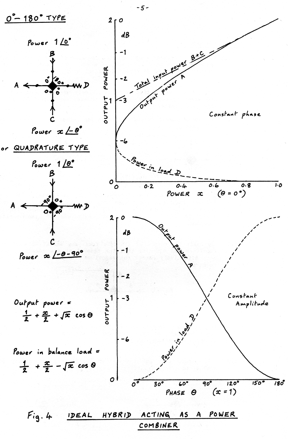
b) Quite large inequalities of amplitude and phase can exist before the level of output power is appreciably less than the level of input power. This is shown in Fig. 4.
5. Uses of Hybrids
In this Section each hybrid is assumed to have ideal characteristics. In Section 6 it is shown how the characteristics of different practical hybrids differ from the ideal.
Some of the uses given below are widely used in broadcasting and communications in general, others are more suited to laboratory tests.
5.1 To provide equal quadrature feeds for turnstile or circularly polarised aerials.
If the reflection coefficients of the two aerials Ael and Ae2 are identical the transmitter at A sees a perfect match because reflections are absorbed in the balance load. Equal power is fed to each aerial regardless of the aerial impedance.
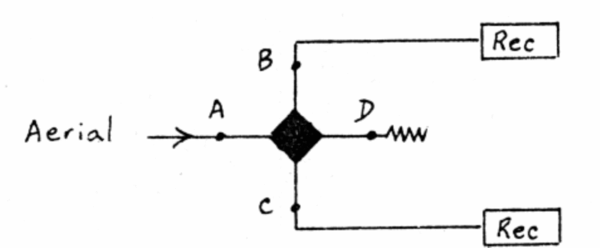
5.2 To split the output of a single receiving aerial between two receivers and ensuring that the removal of one receiver does not effectively cancel the signal at the input to the other receiver.
If the input impedances of the two receivers are equal the input impedance of the hybrid can be matched by the quadrature techniques mentioned in 5.1
5.3 To ensure that one transmitter functions independently of another in a dual transmitter network.
Quite large differences in power or phase can exist between transmitters before the output power falls significantly below the sum power (See 4.2). If one transmitter fails, half of the remaining power appears at the aerial. The isolation between transmitters is dependent on the reflection coefficient of the load at A.
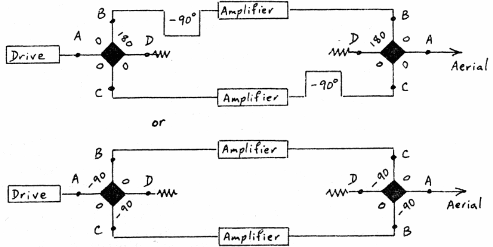
5.4 To provide a dual power amplifier system with low-power-functioning in the event of failure of one amplifier.
If one amplifier fails completely in any way, half of the power of the remaining amplifier appears at the aerial. If the two amplifiers are identical all reflection at the input is absorbed in the balance load on the splitter and all reflection from the aerial is absorbed in the combiner balance load. (This however does not mean that each amplifier sees a perfect output impedance).
5.5 To ensure that near-equal signals are radiated from each half of a split aerial system and to improve the reliability of transmitters and aerials.
In a television transmitting system which uses split transmitters and split high-gain aerials in a populous area it is absolutely necessary to combine signals and to split them again using hybrids, in a radio system it is not so important. The reason for the importance in a television system is that viewers living in the directions of the minima of the vertical radiation pattern of the transmitting aerial receive signals which are the small resultant of large anti-phased contributions from the two half-aerials. Clearly if the two halves of the aerial are fed by separate transmitters which do not have identical video modulating characteristics the received signal will be distorted. The combining hybrid enables the transmitters to be combined without interaction to produce a single output voltage whose waveform is approximately the mean of the two input waveforms, the balancing load absorbs the remainder of the power. The splitting hybrid ensures that identical signals are fed to each half-aerial and provides a balance load to absorb differences between secondary signals which may be reflected by half-aerials. Secondary signals or "ghosts" may still be seen by viewers but the second hybrid ensures that they are not exaggerated in the minima of the vertical radiation pattern by being radiated with some arbitrary amplitude and phase-split between half aerials. (In the limit, when an aerial vertical radiation pattern exhibits complete zeros, the signal received by a viewer in the main beam of the aerial is analogous to the output of a combining hybrid, whilst the signal received by a viewer in the zero of a vertical radiation pattern is analogous to the signal in the balance load of the hybrid).
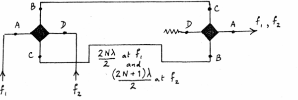
5.6 To form channel combining or splitting networks using unequal-length feeders as frequency-dependent components.
Either type of hybrid may be used provided that the lettering of ports convention of this Report is observed.
The two hybrids are joined back-to-back by two unequal lengths of feeder. The difference in length has to be approximately an even number of half-wavelengths at one frequency and approximately an odd number of half-wavelengths at the other frequency. The cross-loss from one frequency input port to the other frequency input port is theoretically perfect provided that the combined frequency port is perfectly matched. If feeder lengths differ from the ideal this results in losses in the balancing load. Because this combiner contains no resonators it does not give rise to group-delay distortion.
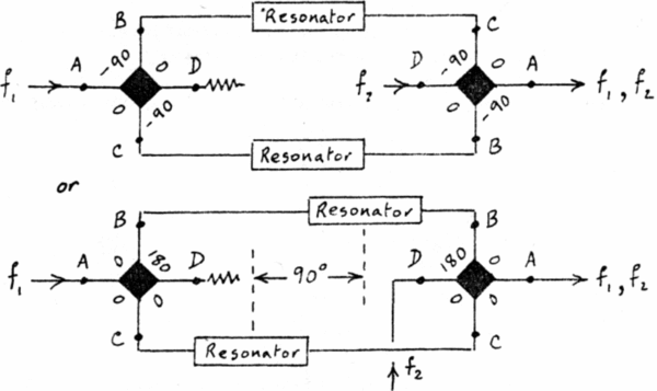
5.7 To form channel combining or splitting networks using resonators as frequency-dependent components.
The two hybrids are connected back-to-back by equal-length feeders as shown. Resonators, spaced as shown, are connected in shunt with each feeder. They appear as short-circuits at frequency f2 and as open-circuits or near open-circuits at frequency f1 Therefore at frequency f1 the signal is split equally by the first hybrid, following which the two half signals pass low-reflection resonators and recombine in phase at the second hybrid. Because the resonators are situated at phase quadrature points on the lines the input reflection coefficient remains low over a wide band of frequencies, reflections being largely absorbed in the balancing load. At frequency f2 the half signals from the right-hand hybrid arrive at the resonators 90° out of phase where they are 100% reflected back in such a phase that they add vectorially at the output port. Cross-loss of f1 to f2 and to some extent f2 to f1 is affected by a mismatch on the output port.
Improved frequency rejection and transmission in each arm of the interconnection feeders may be improved by the use of two resonators spaced a quarter-wave apart. Cross-loss at frequency f1 may sometimes be improved by changing the impedance of the balancing load to reflect a compensating voltage towards the f2 port.
5.8 To form channel combining networks without the use of frequency-dependent components.
Unfortunately this type of combiner can only be used to feed certain special types of aerials such as those which have pairs of elements fed in phase rotation. It can then be arranged so that the rotations at the two frequencies are in opposite senses.
The cross loss between transmitters is highly dependent on the match of the aerial elements.
5.9 To provide all-pass networks for group delay correction.
Suitably designed identical networks provide a loss-less path with a group delay which varies with frequency. If the networks are replaced by switches it is possible to obtain an instant phase change of 180°.
5.10 To form a variable phase changer.
Identical ganged capacitors provide a matched loss-less path through the network. The phase of the output signal can be varied through 180° as the capacitance is varied from zero to infinity.
5.11 To form a variable attenuator.
Identical ganged resistors provide a matched attenuator which can be varied from zero to infinite attenuation as the resistor varies between zero and Z, or between Z and infinity.
5.12 To form a directional coupler with any fixed value of coupling.
Any value of coupling can be achieved by using different lengths of coupling feeder between back-to-back hybrids. The voltage coupling factor k is given by.
k = sin θ/2
5.13 To form a directional coupler with a variable coupling ratio.
Any value of coupling can be achieved by varying identical reactances across the interconnecting feeders. A corresponding circuit can be made with 0°-180° hybrids.
5.14 To create power flow magnification for power tests on a feeder component.
A directional coupler of the type shown in 5.12 is constructed and the forward coupled port is connected to the reverse coupled port by a length of feeder M such that the combined loop formed by M, the hybrids, and L and L + θ in parallel is equal to an integral number of wavelengths. It may then be shown that the magnification factor for power entering the feeder length M is:
where k = sin θ/2
and α = the total numeric voltage attenuation round the loop.
It is necessary for the loop to be well matched for the full magnification to be attained.
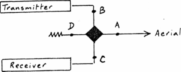
5.15 To form a passive duplexing network in a low-power speech communication link.
Provided that the aerial is matched the transmitter is isolated from the receiver. The disadvantage of the system is that half of the power from the transmitter and half of the signal received by the aerial are lost in the balance load.
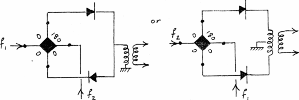
5.16 To form balanced mixers.
Local oscillator f~ amplitude is very much greater than signal amplitude £-. Matched diodes are required for complete cancellation of the local oscillator frequency at the output. Other configurations are possible using two hybrids and suitable diode circuits.
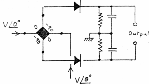
5.17 To produce a phase-sensitive detector.
If perfect matched diodes are used and equal-amplitude signals are applied to A and D the output of the detector is almost linear with phase difference up to +90°. There are ambiguities for phase differences greater than 90°. The output is sensitive to amplitude variations.


