24 GHz
The UK Primary 24 GHz or 1.2cms allocation is 24.000 - 24.050 GHz with the centre of the narrow band operating segment at 24.048 GHz. Wideband operation is centered around 24.025 GHz. In addition there is further secondary spectrum between 24.050 and 24.250 GHz of which the first 100 MHz is not currently permitted to be used in the UK. Consequently the Primary allocation is recommended for all current and future usage.
Contents
Band Plan
See the RSGB 24GHz band plan for full details.
Beacons
There are a number of narrow band beacons in the 24GHz band - see this page for an up to date list.
24 GHz Equipment
The easiest way to get on 24GHz is to modify 23 or 26GHz telecom link equipment.
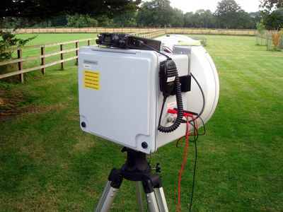
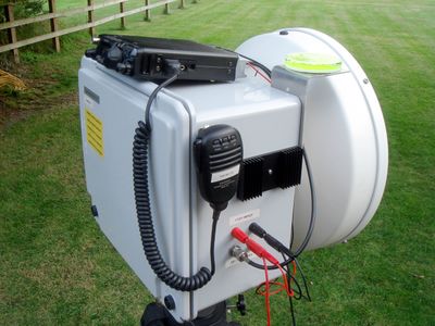
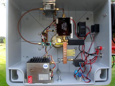
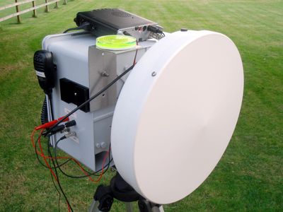
A very good example of this is by G1EHF which shows how simple it is to get on 24 GHz.
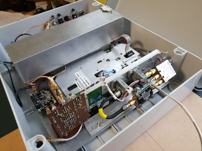
Internally, the transverter largely comprises DMC modules from a ex-23GHz microwave link. The synthesiser and filter have been retuned to the 24GHz band, with the preamplifier, intermediate amplifier and power amplifier connected in series. These are then reversed using a coaxial transfer switch between RX and TX, providing a reasonable noise figure on RX and around 100mW on TX. An MM94P mixer and retuned filter are common to both RX and TX paths.
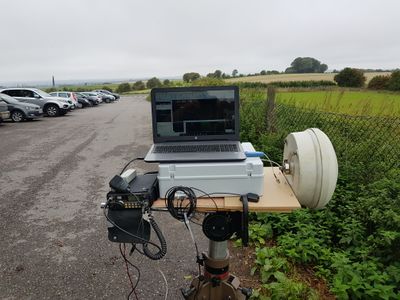
The transverter runs from a single 12V battery and uses an FT817 on 430MHz as the IF. The antenna is by RFS with a gain of around 36dBi.
This transverter runs from a single 12V battery and uses an FT290 on 144MHz as the IF.
Putting a system together
Perhaps the first thing to get is your dish as this determines the hardware form factor of your system.
Then collect and test the modules, typically these will be:
- Local Oscillator block plus multiplier
- Receive module
- Transmit module
- Antenna changeover system - waveguide or high quality SMA relay.
Local Oscillator requirements
To operate on the NB segment at 24,048.2 MHz the following LOs are required:
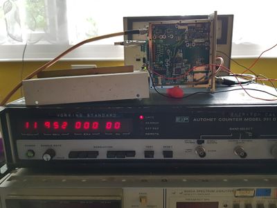
- 144 MHz IF = 24048 - 144 = 23,904 MHz (/2 = 11,952 MHz)
- 144 MHz IF = 24048 + 144 = 24,192 MHz (/2 = 12,096 MHz)
- 432 MHz IF = 24048 - 432 = 23,616 MHz (/2 = 11,808 MHz)
- 432 MHz IF = 24048 + 432 = 24,480 MHz (/2 = 12,240 MHz)
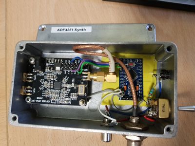
LO generation can alternatively be initiated at lower frequencies with the availability of the versatile Analogue Devices Fractional N Frequency Synthesisers such as the ADF4351 shown below. These fully functional boards requiring just frequency and register programming data can be bought relatively inexpensively from a number of sources including E-Bay sellers. Programming data can be uploaded using a cheap Arduino (Mini) controller to send the required data to the synthesiser registers on power up. The output frequency can be multiplied up to the required LO value although it is likely that for narrowband use a more stable external Frequency Reference source for the synthesiser will be needed from for example, a Leo Bodnar GPS disciplined clock generator or a GPS disciplined OCXO.
DMC Equipment
DMC modules are used by a lot of operators and there is a lot of information available on the web:
- W6BY has compiled a very useful reference list of DMC part numbers = http://www.qsl.net/w6by/parts/dmc.html
- EB3FRN has some useful info and links http://www.eb3frn.net/?p=118 including details on retuning the locked oscillators and retuning the IF = http://www.eb3frn.net/?p=123
- F1CHF has an extensive Powerpoint describing DMC equipment: http://f1chf.free.fr/F5DQK/6_Transverters/24GHz_DMC_bricks_older.pdf
- DMC-110366 Synthesized 20 GHz Microwave Source Operation Manual File:20Syn_BY.pdf
- Notes on Switch setting for DMC 20 GHz source by Rex Allers, KK6MK File:DMC_SW.pdf
- Part number list and pictures of DMC modules (not all 24GHz) available here: http://www.xertech.net/Tech/DMC/DMC_main.html
- Information on the older 11012* modules here Older DMC Modules
- Moving 23 GHz DMC WG Filters up to 24 GHz DMC WG Filters
Elcom synthesisers
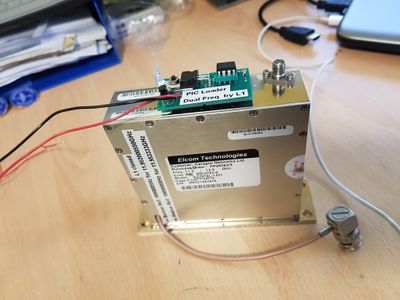
A very common unit to generate the 13GHz LO (doubled to 24GHz) is to use the Elcom 1201 synthesiser available from ebay.
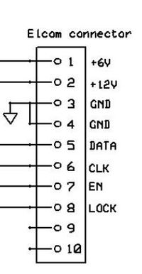
The edge connector has the following connections:
There is a lot of information available on the internet:
- G8CUB has done an excellent article describing their use = http://www.rfdesign.co.uk/microwave/Content/Elcom%20Synth%20article.pdf
- Dave Robinson G4FRE has designed a small PIC interface to program the unit = http://g4fre.com/dfs1201.htm
- Rob M0DTS describes the use of the Elcom 1201 for a personal beacon http://www.m0dts.co.uk/?tag=24GHz
- GM8BJF has developed an Arduino controller for the Elcom: https://gm8bjf.joomla.com/10-articles/11-using-arduino-microcontrollers-to-programme-microwave-synthesisers
- VK2TDN describes the use of an Elcom synthesiser and Thales 23GHz units : http://www.sydneystormcity.com/24GHz.htm
- Croatia Microwave has some tips on getting the Elcom going if yours is faulty : http://croatia-microwave.blogspot.co.uk/2014/10/playing-with-elcom-ceragon-dfs-1201.html
- Locking the Elcom to external 10MHz reference: http://www.vklogger.com/forum/viewtopic.php?f=40&t=10187&start=20#p37834
- Increasing the maximum frequency of the Elcom Synthesiser Elcom Frequency Pulling
- Controlling an Elcom from the Portsdown System https://wiki.batc.org.uk/Portsdown_4_Signal_Generator#Using_an_Elcom_Microwave_Source_as_the_Output_Device
- Scatterpoint Sept 2016 page 7 has an article by Rob M0DTS and Barry G8AGN showing how to modify the Elcom to accept direct commands from an Arduino thereby enabling much smaller step sizes https://www.microwavers.org/scatterpoint/2016/Scatterpoint_1609.pdf
This picture shows an Elcom synthesiser with the PIC loader that provides the programming data on power up.
Nort Synthesized Local Oscillators
The Nort Synthesized Local Oscillators provide a stable LO signal in the 12 - 14 GHz region at about 14 dBm. These were on sale at HamRadio 2018. More details here: Nort SLO
Thales Alcatel 23GHz equipment
A lot of Thales / Alcatel equipment appeared on the second hand market around 2010.
- John G4BAO wrote an article for Scatterpoint March 2010 on using these units on 24 GHz: http://www.sydneystormcity.com/Thales23GHz.pdf
Other station's systems
- OK1VM has a lot of info and pictures but not in English http://www.ok1vm.cz/projekty/24g.htm
- DL4DTU Budowa system description based around DMC modules http://www.sp6gwb.pl/wp-content/uploads/2011/03/Budowa-transwertera-24-GHz.pdf
- 9A4QV describes his system here http://croatia-microwave.blogspot.co.uk/2014/10/eyal-gal-24ghz-transverter.html
- G4NNS describes the Alcatel system and his own portable setup (currently on loan to G8GTZ) http://myweb.tiscali.co.uk/g4nns/24GBits01.html
24 GHz Power amplifiers
Solid State Amplifiers
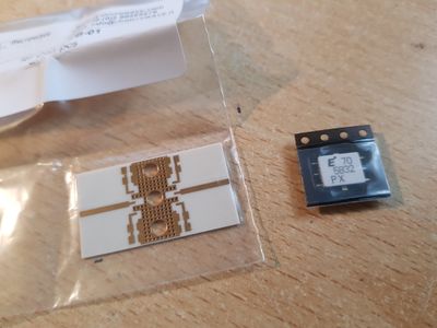
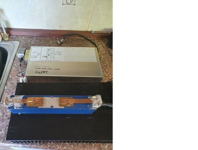
MMIC devices are available that can produce around 1W of output power at 24GHz. For example the EMM5832 device. Ready made PA's such as the Toshiba amplifier pictured come available on the surplus market from time to time. However even power levels as low as 10mW can provide useful performance when coupled with reasonable antenna gain.
Travelling Wave Tubes
here are some scans of TWT databooks. the 1987 issue contains details on the popular RW1127 TWT as described below.
File:Siemens 1987 TWT Databook.pdf
Some details and modifications on the RW1127 TWT and it's Power supply
A 14GHz RW1127 TWT modifed by G4NNS for 24GHz
The "classic" paper on the use of this TWT on 24GHz by DL7YC can be downloaded here
File:dl7yc_man_twta_modifications.pdf
There is also a Powerpoint presentation about the mods here
File:dl7yc_pres_twta_modifications-a_rocky_road.pdf
Much practical initial work in the UK on modifying this TWT was done by Brian G4NNS so here are some of his notes for your further information.
File:dl7yc_modifying_the_rw1127_and_similar_twts_for_24ghz_g4nns.pdf
The RWN32X series of TWT Power supplies
Circuit diagrams and datasheets
Here is a scan of the original German language technical datasheet on the RWN32X series of TWT Power supplies
File:RWN322PTechnisceDaten.pdf
Here is a half-decent English translation of the German text by Google and G4BAO
File:SIEMENS power supply 322P for Traveling wave tubes.pdf
An Arduino-based controller and sequencer for the RW32X series of TWT power supplies
More information to follow!
