Older DMC Modules
Contents
Complete System Based on Older DMC Modules
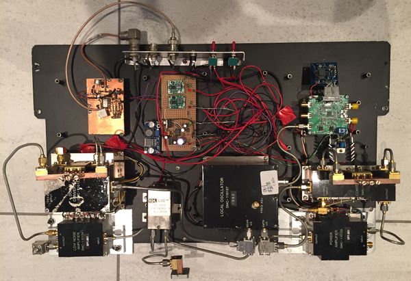
A working system has been constructed using the older DMC modules described below. It uses an ADF5355 local oscillator at 11.805 GHz (modified for minimum phase noise), which is fed into to the amplifier from a satellite LNB to raise its level to +10dBm. A "Franco" doubler to 24 GHz feeds the original DMC oscillator buffer amplifier. The transmit up-converter and PA are used without modification. The receive downconverter is modified for a 438 MHz IF and preceeded by one (or preferably 2) of the original preamps. Filters modified as described here https://wiki.microwavers.org.uk/DMC_WG_Filters are used in the transmit and receive chains. Performance is about 40mW on transmit and 9 dB NF on receive. After modification of the ADF5355, phase noise is very good for SSB and 23 dB MER for DATV.
With the addition of changeover relays and power supplies, the unit has been used for SSB, FM and DATV contacts over 50 km.
Power Amplifier 110123
Small signal gain for the modules that I tested was 7 dB at 24 GHz. I could get about +14dBm of DATV out of them.
Cable Connections:
| Colour | Voltage | Function |
|---|---|---|
| Black | 0 | Ground |
| Yellow | +4.5 | Unknown |
| White | +0.1 | O/P Level Monitor |
| Orange | +8.0 | Unknown |
| Red | +8.0 | Supply |
| Green | +4.5 | +5 supply |
| Blue | -5 | Unknown |
| Mauve | -5 | -5 Supply |
Voltages shown enable the "A" input. One of the +4.5V lines needs to be dropped to 0v to enable the "B" input.
The output level monitor gives about 0.6V when the PA is at full output.
LNA 110124
NF approx 4.5 dB and gain approx 18 dB to each output. Both outputs are driven and seem to be reasonably well isolated.
Cable Connections:
| Colour | Voltage | Function |
|---|---|---|
| Black | 0 | Ground |
| White | +0.1 | O/P Level? |
| Red | +8.4 | Supply |
| Orange | +8.4 | Supply |
Up Converter 110125
LO input needs about +5 dBm at 23.6 GHz. IF needs about + 5dBm at 432 MHz. The gain of the post-filter amplifier is approximately 10 dB at 24 GHz. Max output about +11 dBm.
Cable Connections:
| Colour | Voltage | Function |
|---|---|---|
| Black | 0 | Ground |
| White | +0.1 | O/P Level? |
| Red | +8.4 | Supply |
| Yellow | 0 | ? |
Down Converter 110126
The downconverter has 2 modules. The upper module has an input filter, a diode mixer and a 1542 MHz IF amplifier. The lower module has a diode mixer, a 1612 MHz LO and 70 MHz IF amplifier.
The Lower module was discarded and the upper module modified for a 432 MHz IF by applying the modifications linked here http://www.eb3frn.net/?p=130.
Cable Connections:
| Colour | Voltage | Function |
|---|---|---|
| Black | 0 | Ground |
| Grey | 0 | AGC: 0v for max gain |
| Red | +8.4 | Supply to upper module |
| Yellow | 0 | ? |
| Orange | +8.4v | Supply to lower module |
Local Oscillator 110127
This is a free-running DRO operating in the range 22.5 GHz to 23.5 GHz depending on the specific version number. Output level is approx +7dBm from each output. The DRO is tuned by removing the top screw in the adjustment thread and then tuning the bottom screw; screwing in (clockwise) raises the frequency. The top screw is then replaced to lock the bottom screw. The DRO has 2 outputs and needs -5v and +8.4v supplies. The +8.4v does not appear to be critical as it feeds a 7805 regulator inside the unit. The BNC connector on the case is not connected internally.
Cable Connections:
| Colour | Voltage | Function |
|---|---|---|
| Yellow | 0.5v | ? |
| Mauve | -5 | -5 Supply |
| White | 0 | ? |
| Grey | 0 | ? |
| Red | +8.4 | Supply |
| Black | 0 | Ground |
