Nort SLO
Contents
Introduction
The Nort Synthesized Local oscillator (SLO) runs in the 10 - 14 GHz range and is good for 24 GHz use and useable at 76 GHz. With some modifications the phase noise performance is good enough for QPSK DVB-S DATV at 24 GHz. Output power is in the region of 14 dBm.
The unit contains a transistor VCO controlled by the ADF4153 PLL. The output is feed into a HMC189 passive frequency doubler, then through a BPF, a HMC369 active frequency doubler, through a BPF once again and finally amplified by a HMC441 to provide > +15dBm.
The PLL has a tuning range of around 500Mhz and by moved in the 11 to 13.5Ghz band.
OE2IGL has more information, including pictures of the underside of the PCB
Description
These units use a 20 MHz TCXO and an ADF4153 to control a VCO running at about 3 GHz. This is multiplied by 4, filtered and amplified to achieve about 14 dBm output at 12 GHz. The nominal supply voltage is 12 volts at about 250 mA and the ADF4153 synthesizer needs to be externally programmed through a 3v3 spi connection. The unit runs very hot to the touch.
External connections are through a 2.5mm pitch SPOX header. Pin connections:
| Pin | Connection |
|---|---|
| 1 | spi CLK (3v3) |
| 2 | spi DATA (3v3) |
| 3 | spi LE (3v3) |
| 4 | Lock indication |
| 5 | Ground |
| 6 | +12 V |
Frequency Range
The LOs are supplied for a variety of frequency ranges and typically can be programmed over a 500 MHz range (at the output frequency). Without programming, the LO runs near the bottom end of the frequency range; so for an 11.8 GHz output, free running at about 11.6 GHz is desirable - this would also allow the LO to be programmed as a marker at 12024 GHz.
After removing the case top (by removing all the case fixing screws, and the 2 SMA screws on the opposite side to the VCO adjustment screw), the frequency range can be modified by snowflaking the inverted U-bend that can be seen on the VCO PCB inductor below. The inductor is earthed, so the snowflake can be moved using an earthed soldering iron while the oscillator is running and being measured. The snowflake positioning is very critical.
It was not found necessary to modify the output filters for small output frequency changes.
Programming
The ADF4153 Datasheet defines the commands required for programming the VCO. For experimentation, the unit can be programmed from Raspberry Pi, where it is easy to change the settings. This Python program can be used File:VCO.zip. Once the optimum settings have been found, a simple PIC can be set to program the unit on boot-up.
The unit needs 6 24-bit commands sent in sequence to program it:
| Command | Role |
|---|---|
| Register 3 | Write all zeros to the noise and spur register |
| Register 3 | Select the noise and spur mode required |
| Register 2 | Enable counter reset |
| Register 1 | Load the R divider register |
| Register 0 | Load the N divider register |
| Register 2 | Disable the counter reset |
An example set of codes (for 11805 MHz) is: R3 0x000003, R3 0x0003C7, R2 0x001BC6 R1 0x144281, R0 0x1241F4, R2 0x001BC2. For 12024 MHz, use the codes: R3 0x000003, R3 0x0003C7, R2 0x001BC6 R1 0x144281, R0 0x12C060, R2 0x001BC2.
A PC program to generate the HEX files is available here: https://www.analog.com/en/products/adf4153.html#product-evaluationkit
A simple PIC PCB for programming ADF synthesizers has been designed by G7DOE. It was described in CQ-TV 253 (pp 9 - 12) and further details are here BATC Wiki. This assembler program for the 12F629 will program the Nort LO on one of 4 switch-selected frequencies File:ADF4153-Nortradio.zip. The program actually sends 32-bit words (to allow it to be used with other synthesizers), but setting the first 8 bits of each word to zero allows compatibility with the ADF4153.
The Portsdown 4 Signal Generator has the capability of controlling an SLO directly using a Raspberry Pi 4 and a touchscreen. Details here: https://wiki.batc.org.uk/Portsdown_4_Signal_Generator
Reducing Phase Noise
The phase noise as supplied is too high for QPSK DATV use at 24 GHz. There are a number of steps that can be taken to reduce it:
Programming
- Program the ADF4153 to use the reference frequency doubler
- Program the ADF4153 to use the maximum possible charge pump current
- Reduce the noise on the power supply to the VCO
- Modify the loop filter to reduce the close-in phase noise
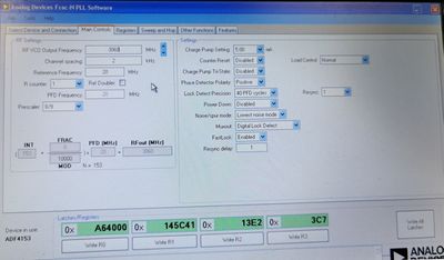
Optimum programming for 12.240GHz with low phase noise recommended by IW1ECD is shown below:
Hardware mods
To reduce the noise on the power supply to the VCO, extra smoothing capacitors can be fitted. The higher the value the better, but there is a limit on what can be fitted inside the casing.
To fit extra capacitors, remove all the case fixing screws, and the 2 SMA screws on the opposite side to the VCO adjustment screw. This will allow you to lift the top of the case off.
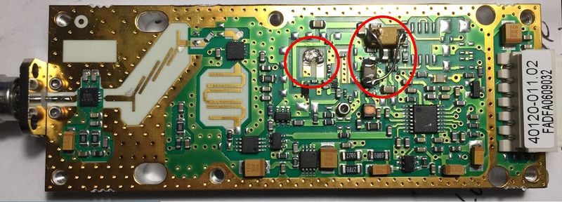
Remove the existing VCO smoothing capacitor C7 (seen in the photo below about half-way between the VCO inductor and the ADF4153), and replace it with a low-ESR 22uf ceramic. Then find the largest surface mount capacitor that will fit in the case, and using thin wires, wire it in parallel with C7. 220 uf is adequate, but improvements could be gained by fitting anything up to 3300 uf - although clearly that is impractical.
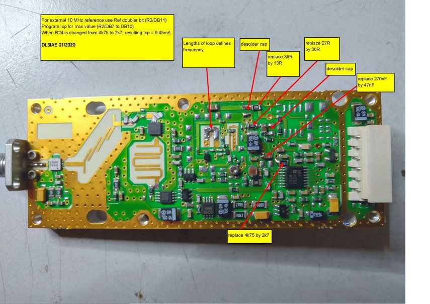
Daniel DL3IAE reports that by making the modifications to the loop filter shown below, the close-in phase noise can be considerably improved.
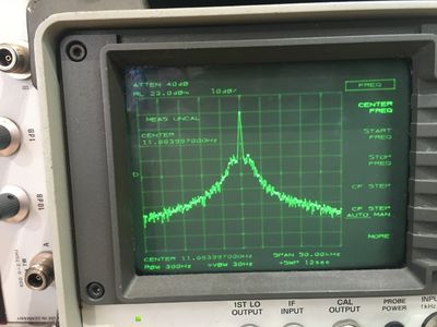
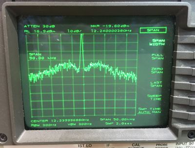
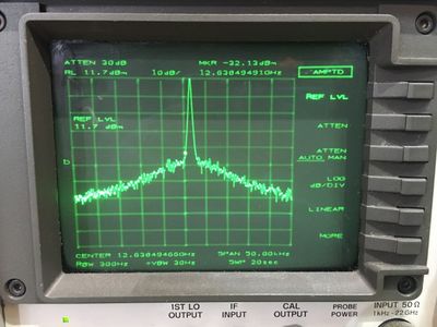
His impressive results are shown in these 3 plots:
Hardware versions
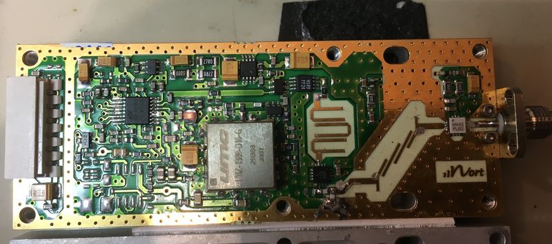
There appears to be a 2nd version of hardware that uses a UMC TCXO and gives much better phase noise results as standard.
Stability
Initial indications are that the frequency stability is good. Drift during warm-up seemed to be less than 10 KHz when used at 24 GHz. No attempt has yet been made to frequency lock the reference.
Doubling to 24 GHz
Using a Franco 24 GHz doubler (details here - scroll down to Page 11), built from a cheap surplus board, 7dBm at 24 GHz can easily be achieved.
