Langstone Project
The Langstone project is an all mode Microwave transceiver covering bands from 70MHz to 5.7GHz running on a Raspberry Pi4 and the Adalm Pluto.
The project started life as an early prototype for the Hayling project and is named Langstone as it is on the way to Hayling Island! Since the demise of the Hayling project, the Langstone has now gone mainstream!
Contents
- 1 Features
- 2 How to build a Langstone
- 3 Hardware - Required Items
- 4 Software and code
- 5 Hardware - Optional Items
- 6 RF Performance
- 7 User Interface
- 8 Settings
- 9 Diagnostics
- 10 Discussion Forum
- 11 Additional Information
- 12 Portsdown Integration
- 13 Using with transverters
- 14 10GHz operation
- 15 24GHz operation
- 16 Prototype demo
- 17 Langstone user experiences
Features
- Touch screen user interface
- All mode (CW/SSB/FM/AM) narrow band transceiver
- 70MHz - 5.7GHz (the unit will actually generate a signal from 47 MHz to 6 GHz)
- Experimental support for 10GHz and 24GHz using Harmonic mixing
- Waterfall spectrum display
- Morse Ident for Beacon Mode.
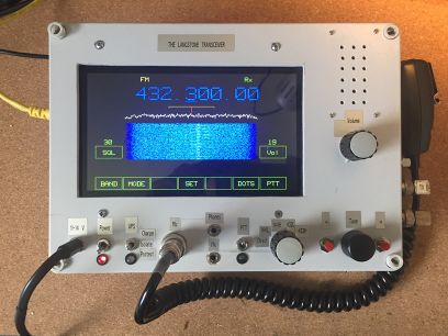
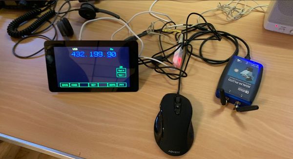
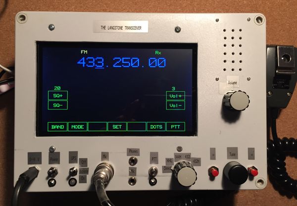
Here is a recent view of the receive screen
How to build a Langstone
- Obtain the items listed in the hardware section of this wiki under 'Required Items'
- Plug all the USB items into the Raspberry Pi
- Create the SD card and install the software software using the instructions found at https://github.com/g4eml/Langstone
- The Pi should reboot and start the Langstone Transceiver. Audio output will be from the USB Dongle Headphone connector. Microphone input will be through the USB Dongle Microphone Input.
- For initial testing the touchscreen PTT can be used.
Hardware - Required Items
This is the minimum required list of items to build a working Langstone.
- Raspberry Pi Model 4 (2GB version is OK)
- Class 10 16Gb micro SD card - Sandisk Ultra is recommended. Low quality cards may not work and will affect performance.
- Adalm Pluto with extended frequency modification. See Extending_the_Frequency_Range_of_the_Pluto
- Official Raspberry Pi 7" Touch screen, DFRobot DFR0550 5" touchscreen or Pimoroni Hyperpixel4 4" touchscreen
- USB audio dongle (see below)
- Wired USB Mouse with scroll wheel or Arduino Pro Micro board with rotary encoder and switches.
USB Audio Adapter
For both the transmitter and receiver the audio device sample rate must be 48000. Devices that do not support this sample rate will not work.
The recommended USB Audio adapter is a cheap (under £5) adapter from eBay like this.
One working example showed up in Linux as:
pi@raspberrypi:~ $ lsusb
Bus 001 Device 005: ID 1b3f:2008 Generalplus Technology Inc.
pi@raspberrypi:~ $
The audio device is named in the GNU Radio Modules Lang_TX.py and Lang_RX.py and alternative devices will need the code modifying before they will work. This can be done by using the set_sound command. See the diagnostics section for more details.
Depending on the microphone being used, an amplifier may be required in front of this adapter. The SL6270C is still available (on eBay) as a cheap solution that provides ALC and filtering.
Software and code
The project is open source using GNU radio modules and all code is available on Github.
The Langstone software along with easy to follow installation instructions is available as a free download from G4EML github.
Integration with Portsdown DATV system
The Langstone is compatible with the BATC Portsdown 4 DATV Tx and Rx system - pre programmed SD cards are available for sale from the BATC shop or the full download is available from the BATC Github.
Updating the software
To update an existing stand-alone installation to the latest version, log in using ssh, paste in these lines (without the comments):
cd Langstone                                        # Make sure we're in the right place
./stop                                              # Stop the Langstone
./update                                            # Download and install the update
sudo reboot                                         # Restart Langstone
If you have the Portsdown build loaded on the same system then use the "Update Langstone" Menu option accessed from Portsdown Menu 3.
Hardware - Optional Items
- MCP23017 i2c module for Digital I/O when using the Hyperpixel Display. Can also be used with the 7" display if preferred to using the Pi GPIO pins.
- Audio Amplifier and speaker. (Volume control might also be useful here)
- PTT Switch and Key.
- Panel mounted rotary encoder and two push buttons for tuning. Third push button for dial lock if required. (Wired to mouse board as described below)
- Relays with drivers for control of external devices.
- External Pre-amps, Power-Amps and Filters for your required bands. Filtering will be required if connecting the Langstone to an antenna. See the Filtering section for more details.
RF band switching and PTT steering
Langstone was designed to use the BATC Portsdown 4 way and 8 way band switching and PTT control hardware.
https://wiki.batc.org.uk/Portsdown2019_hardware#4-Band_Decode_Switch
External rotary encoder for tuning
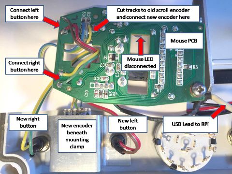
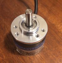
The tuning uses the scroll wheel and buttons on a USB mouse. You can modify this to use a panel-mounted encoder and buttons by taking a mouse apart, cutting the tracks to the scroll wheel encoder and connecting external buttons and an encoder as shown here. If you also want the Dial Lock function then you can add a third button to the middle mouse button.
Arduino Pro Micro Board
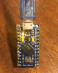
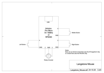
As an alternative to modifying a mouse board it is possible to program an Arduino Pro Micro board (only) to emulate a USB mouse.
One of the benefits of using this approach is the ability to use high resolution rotary encoders for the tuning knob. The Arduino software allows the resolution of the encoder to be adjusted to suit the Langstone.
Full details can be found at https://github.com/g4eml/Langstone-Mouse
The encoder should be connected to the labelled pins on the Arduino Pro or RP2040 board as shown.
DFRobot DFR0550 5" Touchscreen
As a smaller and cheaper option to the official Raspberry Pi 7" Touchscreen the DFRobot DFR0550 screen appears to be compatible. A special install script is provided for this display install_dfr0550.sh This script is identical to the normal Langstone install.sh script with the exception that it does not add the line "lcd_rotate=2" to the /boot/config.txt file. If you have a working Langstone system and wish to change to the DFR0550 display you will just need to edit /boot/config.txt and remove the "lcd_rotate=2" line.
The Portsdown system does not officially support the DFR0550m however it does appear to work OK.
Hyperpixel4 4" Touchscreen
As a smaller alternative to the official Raspberry Pi 7" touchscreen the software has additional support for the Pimoroni Hyperpixel4 4" touchscreen.
This screen requires special drivers to be installed. This is included in the install_hyperpixel4.sh script on the github page.
Note that this screen is not currently supported by the Portsdown project, so a combined Portsdown/Langstone is not possible if you choose this screen.
MCP23017 i2c expander
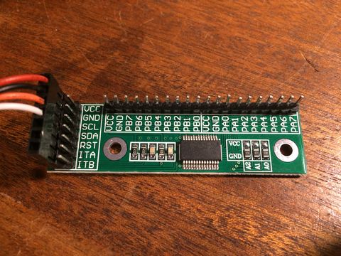
Because the Hyperpixel4 screen uses virtually all of the Raspberry Pi GPIO there is no spare capacity for the Hardware PTT, Key and Band Select inputs and outputs. To provide more I/O Pins the software supports an external i2c connected expander board using the MCP23017 chip. This provides 16 digital input or outputs and is connected to the Hyperpixel4 display i2c connector. These modules are available at low cost (under £5) from eBay.
The connections for the module are shown in the table below.
The module needs to be configured as device address 20. This is done by grounding pins A0, A1 and A2. On some modules this is the default setting on others you may have to add jumpers.
It can be used on either the Hyperpixel4 display by connecting to the built in i2c connector or on the Raspberry Pi when using the 7" display by connecting to the GPIO Pins.
| Signal | HyperPixel4 | Pi GPIO Pin |
|---|---|---|
| VCC | 3V3 | 1 |
| GND | GND | 6 |
| SCL | SCL | 5 |
| SDA | SDA | 3 |
| RST | N/C | N/C |
| ITA | N/C | N/C |
| ITB | N/C | N/C |
N/C= No Connection
You can check that the module is recognised by entering one of the following commands:-
sudo i2cdetect -y 11 (for the 4" display)
sudo i2cdetect -y 1 (for the 7" display)
You should see device 20 present in the displayed matrix
    0  1  2  3  4  5  6  7  8  9  a  b  c  d  e  f
00:          -- -- -- -- -- -- -- -- -- -- -- -- --
10: -- -- -- -- UU -- -- -- -- -- -- -- -- -- -- --
20: 20 -- -- -- -- -- -- -- -- -- -- -- -- -- -- --
30: -- -- -- -- -- -- -- -- -- -- -- -- -- -- -- --
40: -- -- -- -- -- -- -- -- -- -- -- -- -- -- -- --
50: -- -- -- -- -- -- -- -- -- -- -- -- -- -- -- --
60: -- -- -- -- -- -- -- -- -- -- -- -- -- -- -- --
70: -- -- -- -- -- -- -- --
GPIO Pins
The following table shows the assignments for the digital inputs and outputs.
The PTT input and the Key input must have pull up resistors connected between the relevant pin and 3.3V.
The PTT Switch and Key should ground these pins when activated.
The Tx and Band Outputs are 0v for off and 3.3V for on. These outputs will need to be externally buffered to drive relays etc.
| Function | GPIO Pin | Pluto GPO | MCP23017 |
|---|---|---|---|
| PTT Input | 11 | N/A | PA0 |
| Key Input | 12 | N/A | PA1 |
| Tx Output | 40 | GPO0 | PA7 |
| Band D0 Output | 28 & 32 | GPO1 (optional) | PB0 |
| Band D1 Output | 35 | GPO2 (optional) | PB1 |
| Band D2 Output | 7 | GPO3 (optional) | PB2 |
| Band D3 Output | 22 | N/A | PB3 |
| Band D4 Output | 16 | N/A | PB4 |
| Band D5 Output | 18 | N/A | PB5 |
| Band D6 Output | 19 | N/A | PB6 |
| Band D7 Output | 21 | N/A | PB7 |
Note that the GPIO output for the Band 0 bit is duplicated on GPIO pins 28 and 32. This is to retain compatibility with the Portsdown Project. Either pin can be used.
The Band D0 D1 and D2 pins can optionally be copied to the Pluto GPO1 GPO2 and GPO3 pins. This option is set in the Settings Menu. If you have the Tx Relay add on board fitted in your Pluto then you will need to set this option to 'No'. This is because the relay board uses GPO1.
RF Performance
Typical Power Output
These are typical output powers from the Pluto, measured on NBFM. SSB outputs peak near these levels. The output power drops off at either end of the range because we are using the Pluto outside of its design specification.
| Frequency | Output Power |
|---|---|
| 70MHz | - 6.0 dBm |
| 144 MHz | + 1.0 dBm |
| 432 MHz | + 3.5 dBm |
| 1296 MHz | +2.5 dBm |
| 2400 MHz | + 1.0 dBm |
| 3400 MHz | 0.0 dBm |
| 5760 MHz | -3.0 dBm |
| 10368 MHz | -30 dBm |
Filtering
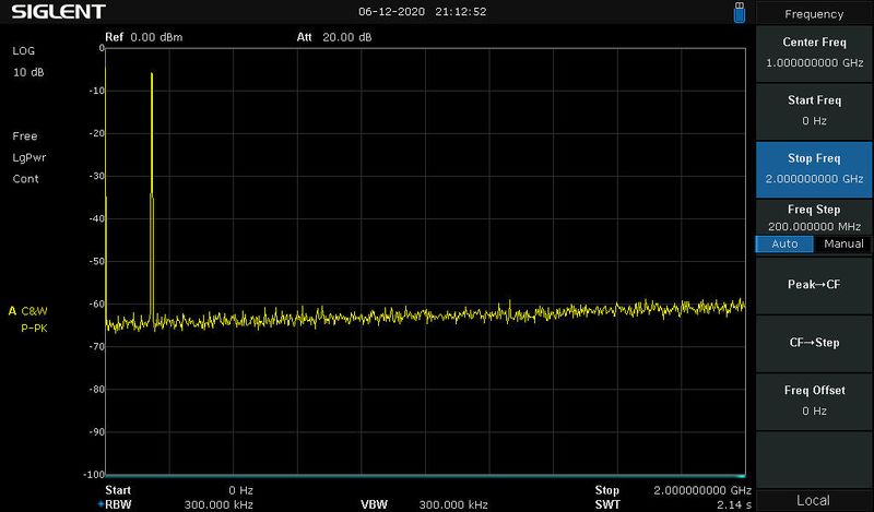
The Pluto output is an unfiltered square wave. This has a very high harmonic content at all of the odd harmonics. External filtering is essential if you are going to connect the Langstone to an antenna.
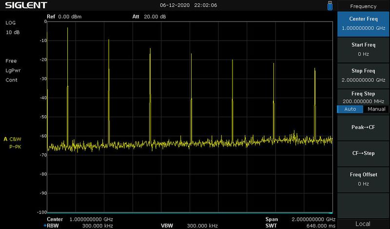
As an example the following picture shows the unfiltered output of the Pluto between 0 and 2GHz when operating on 144MHz.
The left hand peak is the wanted signal at 144MHz followed by peaks at 432MHz, 720MHz, 1008MHz, 1296MHz, 1584MHz and 1872MHz which are the 3rd, 5th, 7th, 9th, 11th, and 13th Harmonics.
Adding a 144MHz bandpass filter results in a much cleaner spectrum as shown in the following picture.
A good low pass filter with a cut-off between 144 and 432 would also be suitable.
This example is for 144MHz but the same applies to any frequency covered by the Langstone. You will need a bandpass or low pass filter for each band you wish to use.
To prevent problems when feeding a power amplifier it is probably best to include a low power band pass filter between the Pluto and the Amplifier and a high power Low pass filter after the amplifier.
User Interface
- The Langstone is intended to be used with the touchscreen and a mouse scroll wheel and buttons. The scroll wheel is used for tuning and adjusting values, the mouse buttons select the digit to be tuned. Mouse movement is not used. Normally a tuning knob will be connected to the scroll wheel. For this description 'Tuning Knob' and 'Scroll Wheel' are the same thing.
- The Middle mouse button can also be used to select and deselect the Dial Lock. This is useful when using tuning knobs without detents. LOCK is displayed above the frequency display in red if the Dial Lock is on. Touching any frequency digit will also remove the dial lock.
- If you do not have a Middle mouse button fitted you can also activate the Dial Lock by pressing both mouse buttons simultaneously (within 200ms).
- The screen always shows the currently tuned frequency in large digits. One digit will be underlined, this is the digit that will be adjusted with the tuning knob. Touching a digit on the screen or using the left and right mouse buttons will move the underline.
- Below the frequency display is the spectrum display and waterfall. This shows signals + and - 20Khz from the centre frequency. A red vertical line shows the tuned frequency and an orange bar shows the receiver bandwidth. When transmitting the waterfall and spectrum will display the transmitted signal. This is taken from the digital drive signal to the Pluto and does not necessarily reflect the actual transmitted spectrum.
- The top left of the screen shows the S meter. This indicates the maximum level detected within the receiver bandwidth. Zero Level is adjusted in the Settings menu. Calibration is 6dB per S-Point. Touching the S-Meter will change the displayed values between S Units and dBs. Using the dB setting may be more useful when comparing signal levels or aligning antennas. When transmitting this meter changes to show the relative output power. This is purely for indication and does not reflect the actual power output of the Pluto. It does not reflect the setting of the Tx attenuator.
- Status Indicators are displayed above the frequency display.
- When operating is SSB or CW the RIT button is displayed to the right of the frequency display. Touching this button turns it red and allows the RIT to be tuned using the tuning dial. touching it again return to normal tuning. Touching the 'Zero' button zeros the RIT and returns to normal tuning.
- To the right of the Waterfall is the volume button. Touching this button allows the volume to be adjusted using the tuning dial. Touching it again return to normal tuning.
- When operating in FM Mode the Squelch Button is displayed to the left of the waterfall. Touching this button allows the squelch to be adjusted using the tuning dial. Touching it again return to normal tuning.
- At the bottom of the screen are the function buttons.
- BAND
Selects a popup menu of the first 6 of the 12 available bands. Selecting More.. will display the second 6 bands. Touching any band button will switch to that band. Note:- the bands are really just 12 separate VFOs. Any one can be set to any frequency. The label on the button is taken from the last used frequency in MHz.
- MODE
Selects a popup menu of the available modes, USB, LSB, CW, CWN, FM, and AM. Touching any button will switch to that mode. CWN uses a narrow filter centred on 800Hz.
CW mode has semi break-in. When operating in CW mode the Langstone will switch to transmit when the key is pressed and will return to receive after a short delay, configurable in the setup menu.
- DUP
Displayed when in FM mode. Turns on the repeater shift. Whilst transmitting this button changes to '1750', touching this button transmits a 1750Hz access tone for repeaters.
- SET
Selects the Settings mode described below. Whilst in the settings menu the right hand button shows 'Shutdown', touching this button will close down the program ready for power off.
- BEACON
Selects a popup menu with options of DOTS or CWID. Selecting either of these switches to CW Mode and transmits a constant stream of dots or a user defined Morse Ident. Used for microwave bands to provide an antenna alignment signal. Touching the button a second time returns to receive with the mode that was previously selected. If operating on SSB the beacon is sent with a frequency offset of 800Hz, this allows the receiving station to hear the beacon without having to retune. Beacon mode can also be cancelled by pressing the Microphone PTT.
- PTT
Manually turns on the transmitter. Touching the button a second time returns to receive. Manual PTT is also cancelled by pressing the Microphone PTT.
Settings
Touching the SET button will display a series of adjustable values. Step through the available values using the NEXT and PREV buttons. Adjust the values using the tuning knob (Mouse Scroll Wheel). For some settings the left and right mouse buttons select the digit to be adjusted. Touching the MENU button exits from the settings menu. Most settings have a different value for each band but some are common to all bands.
The available settings are as follows:-
- SSB Mic Gain
Adjusts the level of the microphone input when in SSB mode. Common to all bands.
- FM Mic Gain
Adjust the level of the microphone input when in FM Mode. Common to all bands.
- Repeater Shift
Sets the repeater shift when working in FM Duplex mode.
- CTCSS
Sets a CTCSS Tone for FM Transmission only. There is no CTCSS decoder for receive. Selecting a tone setting of 0.0 Hz disables the CTCSS Tone.
- Rx Offset
Applies an offset to the displayed frequency. This is primarily used with transverters or transponder satellites such as QO-100. The display shows the final frequency which will be received by the transverter.
- Rx Harmonic Mixing
Can be set to X1 or X5. Normally set to X1, when set to X5 the receiver will use the 5th Harmonic of the LO for reception. See the description for 10GHz use for more detail.
- Tx Offset
Applies an offset to the displayed frequency when transmitting. This is primarily used with transverters or transponder satellites such as QO-100. The display shows the final frequency which will be transmitted by the transverter.
- Tx Harmonic Mixing
Can be set to X1, X2 or X5. Normally set to X1, When set to X2 the output frequency will be half of that displayed. This is for use of an external doubler such as used in the Hydra Modules by OE8FNK. when set to X5 the receiver will use the 5th Harmonic of the LO for reception. See the description for 10GHz use for more detail.
- Band Bits (Rx)
This is the binary value that will be output to the band select outputs when the current band is selected and receiving. Any pattern can be selected for operation of external relays etc.
- Band Bits (Tx)
This is the binary value that will be output to the band select outputs when the current band is selected and transmitting. Any pattern can be selected for operation of external relays etc. Selecting different patterns for Rx and Tx can be used to enable band specific PTT signals.
- Copy Band Bits to Pluto
This option can be set to 'Yes' or 'No'. When set to 'Yes' band bits D0, D1 and D2 will be copied to the Pluto GPO1, GPO2 and GPO3 pins. This is to allow the connection of band switching hardware directly to the Pluto. If you have the internal Pluto TX relay board fitted then you must leave the option set to 'No' for the relay to work correctly.
- FFT Ref
This sets the reference level for the Spectrum display and Waterfall. External Pre-amps will affect the noise level with no signal, you will need to adjust the refence level to give a suitable display.
- Tx Att
Adjust the level of the Transmitter output. This has a range of 0 to -89 dB. This is to allow the signal level to be adjusted to suit external amplifiers. Note that the setting of this attenuator is not reflected in the onscreen transmit output meter or Spectrum display.
- S-Meter Zero
This sets the signal level that is displayed as S0 on the display. It should be adjusted to compensate for any pre-amplifier noise.
- SSB Rx Filter Low
This sets the low frequency cut-off of the SSB receive filter. Normal setting is 300 Hz. Common to all bands.
- SSB Rx Filter High
This sets the high frequency cut-off of the SSB receive filter. Normal Setting is 3000 Hz. Common to all bands.
- Rx Gain
Adjusts the Pluto Rx gain setting. This is the overall RF gain of the Pluto Receiver. The default and recommended setting is 'Auto', the Pluto will then adjust its gain automatically to ensure no input signal exceeds the maximum allowable value. Changing the setting from 'Auto' allows the gain to be set manually and fixed at that level. The available range of gain settings depends on the frequency selected (this is the default Pluto behaviour). 70-1300 MHz= -1dB to 73dB, 1300-4000 MHz= -3dB to 71dB, 4000-6000 MHz= -10dB to 62dB. The 'Auto' mode is selected by setting one click above the maximum gain value.
- CW Ident
Defines the Morse code string that is sent (up to 40 characters) when using the Beacon CWID feature. Characters are selected by rotating the tuning knob. The selected character is coloured green. The left and right bottons select the character. Only characters A-Z 0-9 / and space can be selected. To delete unwanted characters set them to Space. Trailing spaces are deleted.
- CWID Carrier
Sets the number of seconds between CW Idents. The key is kept down during this period to produce a constant carrier for antenna alignment.
- CW Break-In Hang Time
Sets the time that Langstone remains in Tx after the morse key is released. Adjustable between 500 and 2000 ms.
Diagnostics
Overview
If you are experiencing problems in getting your Langstone working there are some diagnostic programs included to try to identify the most common problems.
- Pluto_Test is used to check the connection between the raspberry Pi and the Adalm Pluto. It also checks the throughput to make sure it is working fast enough.
- set_sound is a simple script to find and select the sound device to be used by Langstone.
- set_pluto is a simple script to change Langstone to match the IP address or name of the Pluto.
- HW_Test is used to check for correct operation of the Mouse, Touchscreen, GPIO and MCP23017 (if Fitted).
To run any of these programs you first need to SSH into the Pi. Then enter the following commands:-
cd ~/Langstone
./stop
./set_sound
./set_pluto
./Pluto_Test
./HW_Test
Pluto_Test
This program checks that the Pluto is connected and is responding to the address 'ip:pluto.local'. This is the default name for the device and should be discoverable regardless of the actual IP address. If the Pluto is found then the program runs a short test which sends 1000 commands to the Pluto and times how long it takes to respond. A working system should return a figure of approximately 1900 commands per second. Significantly less than this indicates a problem with the USB connection or the Pluto's power supply. For example connecting the Pluto via a USB hub can reduce this to only about 200 commands per second which is too slow to be usable.
If you are having reliability issues with your Pluto regularly disconnecting or becoming unavailable then try reducing the power supply voltage. It has been found by several people that the Pluto is more reliable at a lower voltage. Possibly as low as 4.7V. One way to achieve this without reducing the voltage to the Pi would be to modify the USB cable feeding the Pluto. Carefully strip the cable and identify the positive lead, cut this and insert a series Schottky diode such as a 1N5817.
set_sound
This script searches for suitable sound card drivers. These will begin with 'hw:'. The script will list all suitable drivers and allow you to enter the number of the one you wish to use. This automatically modifies the entry in Lang_TX.py and Lang_RX.py.
When using the recommended configuration only one driver will be listed. This will be 'hw:CARD=Device,DEV=0'.
set_pluto
This script allows you to enter a new name or IP address for the Pluto. The script will then make the necessary changes to the Langstone files. You can either use the network name (default = pluto.local) or the IP address (default value = 192.168.2.1) to identify the Pluto. Some networks may have problems resolving the name. If that is the case then try using the IP address instead.
HW_Test
This program is used to check correct operation of the Mouse, Touchscreen, GPIO inputs and MCP23017 inputs. It first tests to see what devices are connected and then runs a continuous loop reporting any changes it sees.
While the program is running you should exercise the hardware as follows:-
Touch the touchscreen a few times and make sure the touches are reported.
Operate the Mouse Scroll Wheel (Tuning Knob) and left and right buttons and make sure they are reported correctly.
Ground the PTT and KEY inputs on the GPIO pins or MCP23017 pins and make sure they are reported correctly.
When you have finished testing you need to enter <control> C to exit the program.
Log Files
There are also several log files created by the Langston programs. In the event of problems it is worth looking at these files as they may give a clue to the cause. These are simnple text files that may be viewed with the more or cat commands.
/tmp/LangstoneGUI.log Log file for the main Langstone User Interface.
/tmp/LangstoneRX.log Log file for the GNU Radio Lang_Rx.py program (Note: an occasional 'ERROR: WRITE ALL: -9' is normal)
/tmp/LangstoneTX.log Log file for the GNU Radio Lang_Tx.py program
Discussion Forum
There is a discussion forum about the Langstone hosted on the BATC Forum here: https://forum.batc.org.uk/viewforum.php?f=129
Additional Information
Extending the Frequency Range of the Pluto
As supplied the Adalm Pluto has a frequency coverage of 325-3800 MHz. This range can be extended by a software modification. Although it is then operating outside its specifications the Pluto can then be used between 70 and 6000 MHz.
To perform the modification you need to connect directly to the Pluto using a serial comms program such as putty.
Connect the Pluto to a Windows PC USB port. Wait for it to be recognised then use device manager to identify which Com port number has been assigned to the Pluto.
Open Putty and make a connection to the Pluto Com port. Speed 9600.
log in as user root
The password is analog
Enter the following commands:-
fw_setenv attr_name compatible
fw_setenv attr_val "ad9364"
pluto_reboot reset
After doing this your Pluto will have an extended frequency range.
Changing Pluto IP address
The Pluto comes pre-configured with the IP address 192.168.2.1. and a network name of pluto.local. If this conflicts with your local network, this Analog Devices web page describes how to change it by editing the config.txt file on the Pluto https://wiki.analog.com/university/tools/pluto/users/customizing?rev=1575147632
The Langstone code uses the default network name 'pluto.local' to communicate with the Pluto. This should work regardless of the actual Pluto IP address. If you change the name of your Pluto you will need to also change the setting in Langstone.
The set_pluto command can be used to make the necessary changes.
If you load the Portsdown system alongside the Langstone, you will need to set the revised Pluto IP address in the Langstone Configuration on the Portsdown Menu 3. This is to enable a smooth transition between Langsone and Portsdown functionality.
Inverting the Screen Image
If you have used an official Raspberry Pi Case, you may find that the Langstone screen image is inverted. To correct it, simply edit the file /boot/config.txt (using sudo):
Remove or comment out the line
lcd_rotate=2
Then save and restart.
Portsdown Integration
The latest version of the Portsdown DATV System, the Portsdown 4, is compatible with the Langstone transceiver when using the 7" touchscreen. If you want both capabilities in one sytem, simply build the Portsdown 4 as detailed here https://wiki.batc.org.uk/Portsdown_4 and then go to Menu 3, Langstone Config and select "Install Langstone". You can then select the Langstone from Menu 2 of the Portsdown and return to the Portdown from the Settings menu of the Langstone.
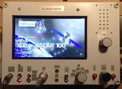
Here is G8GKQ's Portsdown/Langstone receiving the QO-100 DATV Beacon.
Using with transverters
The Langstone transceiver is designed to be used with transverters for the higher microwave bands.
The Tx Offset and Rx Offset settings are used to enable the Langstone frequency display to show the final output frequency of the transverter. As most transverters are symmetrical the same value should be entered for both Tx and Rx Offset.
The Band Bits outputs can also be programmed and used to select the transverter using an external driver and relays. Different band bit patterns can be programmed for Receive and Transmit. This can be used to provide band specific PTT signals.
An example of calculating the required offset value for a transverter
Transverter Output Frequency =10368 MHz
Transverter IF Frequency =144 MHz
Required Tx and Rx offset= 144 - 10368 = -10224 MHz
You should set the Tx Offset and the Rx Offset to -10224.0000 in the settings menu.
You should then exit from the settings mode and set the dial frequency to 10368.000
You can then return to the settings menu and check the offsets. The actual Tx and Rx frequencies will be displayed, in this example they should both read 144.000 MHz.
Using with QO-100
The Langstone transceiver has a special mode for use with linear transponder type satellites such as QO-100.
A typical QO-100 station will transmit on 2.4GHZ and will receive using an external LNB which down converts the 10489 MHz satellite downlink to 739 MHz.
Different Tx Offset and Rx Offset settings are used to enable the Langstone frequency display to show the satellite downlink frequency.
When different Tx and Rx offsets are entered the display will show 'SAT' at the top of the display. A additional 'MONI' button will also appear in the menu. This button is used to listen to your own downlink whilst transmitting.
An example of calculating the required offset values for QO-100
Satellite Downlink Frequency = 10489.6 MHz
Satellite Uplink Frequency = 2400.1 MHz
LNB Local Oscillator Frequency = 9750 MHz
Required Tx offset= 2400.1 - 10489.6 = -8089.5 MHz
Required Rx offset= -9750 MHz
You should set the Tx Offset and the Rx Offset to these values in the settings menu.
You should then exit from the settings mode and set the dial frequency to 10489.6000
You can then return to the settings menu and check the offsets. The actual Tx and RX frequencies will be displayed and checked, in this example they should read 2400.1000 MHZ for Tx and 739.6000 MHz for Rx.
10GHz operation
Although the upper frequency limit of the Pluto (with expanded frequency mod) is 6GHz it has been found that it also produces significant harmonic content. This can be utilised to further extend its coverage to include the 10Ghz band.
Two experimental options have been added to the Langstone setup menus. These are called 'Rx Harmonic Mixing' and 'Tx Harmonic Mixing' and can be set to 1X or 5X. 1X is the default and is the normal mode for Bands up to 6 Ghz.
Selecting the 5X mode causes the Langstone to program the Pluto for one fifth of the displayed frequency. So for a displayed frequency of 10368 Mhz it will be programmed for 2073.6 MHz. The fifth harmonic of this signal is then modulated to provide a low level signal at 10368. A similar thing happens on receive where the 5th Harmonic of the LO is used.
Note that when using Harmonic mixing you need to ensure that Tx Offset and Rx Offset are set to zero.
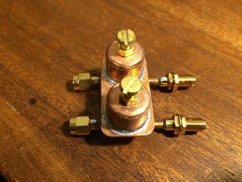
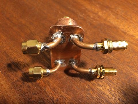
The output spectrum contains both a signal at 2073.6 MHz and a lower power signal at 10368 MHz. To make use of the higher frequency it is necessary to externally filter out the lower one. This can be done with simple pipecap filters as shown below or even simply by feeding a waveguide 16 antenna which will not pass the lower frequency.
The output power and also the receive sensitivity are much lower than for normal 1X use. Some initial experiments have shown that around 30dB of external gain is required in both the transmit and receive paths. With this extra gain the transmit power will be approximately 0dBm (1mW) and the receive sensitivity will be on a par with other systems.
Even without amplification it should be possible to have short range QSOs on 10 GHz.
Fred, OE8FNK has developed several add on boards for the Pluto to enable use on 10GHz. Details of these can be found at http://www.uhf.at/hydra
The Initial Hydra boards use a frequency doubler for transmit and a satellite down converter for receive. This means that any mode can be received but only FM or CW can be used for transmit. This is because the doubler will not work correctly with an SSB signal. Fred is also developing a Harmonic Hydra which should work using the Harmonic mixing modes of the Pluto which will then allow it to be used with any mode.
24GHz operation
The comments above for 10GHz also apply to 24GHz. The output power and receive sensitivity on this band are extremely low, however it can be used as a test signal and receiver for short range testing of other equipment.
Prototype demo
Colin, G4EML demonstrated an early prototype in early November 2019 running on an RPi4 with USB audio dongle and a Pluto SDR enabling NB operation all bands from 70MHz to 5.6Ghz!
The prototype was running a touchscreen gui written in c controlling gnu radio.
Langstone user experiences
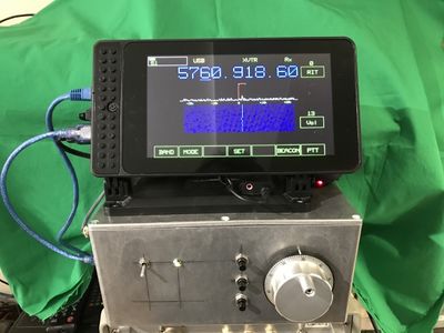
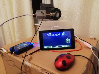
- Dave G4FRE has used the Langstone for QSOs on 3.4GHz and received the GB3OHM beacon on 5.7GHz as shown here.
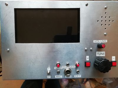
- Dave G4FRE has now put his parts in a box with 1 watt 144/432MHz amplifier, audio amplifier and speaker, keyer IC and high stability 50MHz reference.
- Dave G8GKQ has received the GB3USK beacon on 23cms and is currently building a Langstone into a box....
