Waveguide
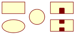
Waveguide is a precision tubular form of transmission line used at microwave and millimetre wave frequencies. The most common form is rectangular cross-section but there are others as illustrated and described below.
The waveguide wall contains and guides propagating fields once the operating frequency is above the cutoff point. All waveguides are dispersive and have varying impedance and group delay vs frequency.
Contents
Rectangular
Standard rectangular waveguide is typically twice as broad as high, although the ratio can vary slightly for historic reasons. It cuts on when the width, a, is half of the free-space wavelength.- Width: The internal width determines the cut-on wavelength of the dominant TE10 mode as well as the TE20 overmode frequency.
- Height: The height influences its impedance. For either matching purposes or to save weight there are occasions where reduced or half-height waveguide is used
The recommended range is typically from 1.25 to 1.95 of the cut-on frequency unless measures are taken to prevent TE20 overmoding.
- UKuG Website: Table of Rectangular Waveguide Sizes
Circular
Circular waveguide is often used in antenna feeds, but can also be used in low loss feeders and rotary joints Its symmetry can support dual or circular polarisation, but also can result in indeterminate mode purity/alignment in longer lengths. The fundamental mode in circular waveguide is TE11 (akin to TE10 in rectangular guide). Circularly symmetric modes are:
- TM01: The electric field is orthogonal at all points to the wall and is a key mode for rotary joints to give stable performance vs rotation
- TE01: This uniquely has no electric field at the wall edge and in theory has zero attenuation. Whilst its creation and sustainment takes care, it can be used for very low losses over many metres
- TE11o: This is a spinning circularly polarised version of TE11. This is achieved by careful use of dual feeds or phasing vanes
Elliptic
Elliptic waveguide is used in either rigid or flexible forms to provide a more stable mode environment than circular. The most common application is in long feeds to dishes.
Ridged
A capacitive metal ridge in the middle of a rectangular waveguide lowers its cutoff frequency (and impedance) whilst having only a modest effect on TE20. The result gives TE10 operation over an octave bandwidth (making it popular for EW applications). The format can be either single ridge from one broad wall, or a more symmetric double ridge from both. Examples:-
- WRD500D36 - Double Ridge 5.0-18 GHz (3.6:1 bandwidth ratio)
- WRD750D24 - Double Ridge 7.5-18 GHz (2.4:1 bandwidth ratio)
- WRD180C24 - Double Ridge 18-40 GHz (2.4:1 bandwidth ratio)

